References
Bereznicki T, Patel R, Clark M. Revisiting the functionally generated path technique: is this an aid to predictable digital occlusal design? Part 1. Introduction and background. Dent Update. 2022; 49:371-378
Bereznicki T, Patel R, Clark M. Revisiting the functionally generated path technique: is this an aid to predictable digital occlusal design? Part 2. The technique. Dent Update. 2022; 49:462-470
Top Tip: A technique to fabricate a new crown around an existing removable partial chrome denture
From Volume 2, Issue 2, June 2025 | Pages 101-105
Article


When planning to provide a partial chrome cobalt denture for a patient, factors to be taken into consideration include the path of insertion and the abutment teeth that will provide both support and retention for the prosthesis.
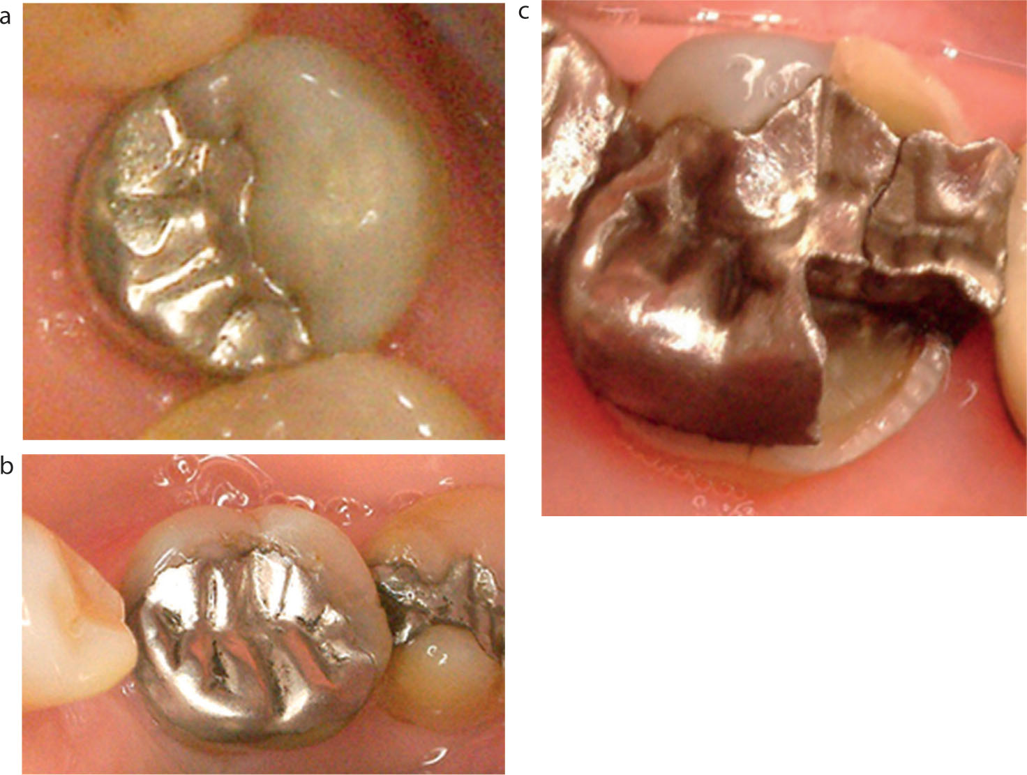
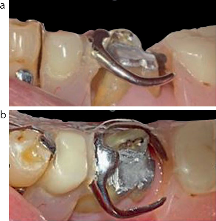
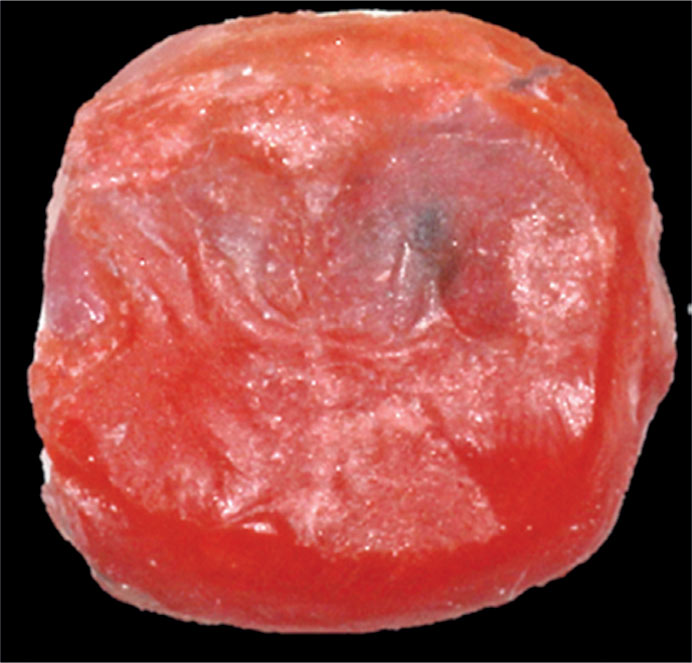
Although old, extensive restorations, such as the 20+-year-old amalgams shown in Figure 1, can provide good service, in the long term, these teeth can be vulnerable to spontaneous restoration fracture, cuspal fracture or both (Figure 1c).
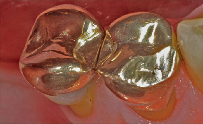
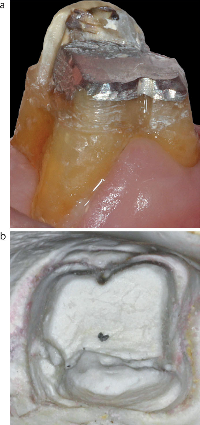
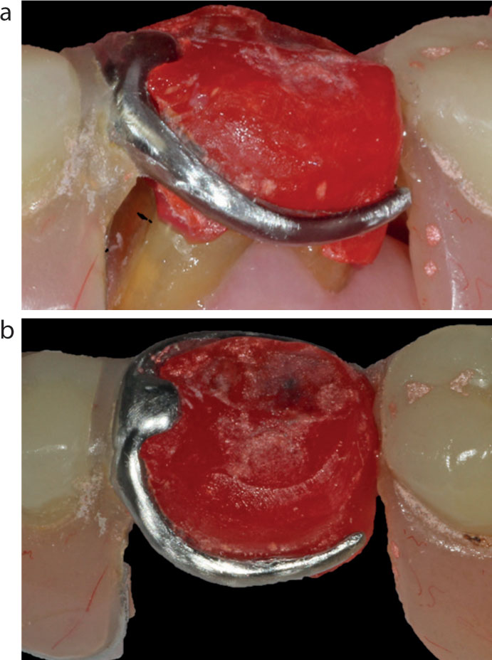
If the teeth to be involved in the design of the denture are heavily filled and to be used as abutments, it is generally prudent to consider the provision of an indirect restoration before starting the steps involved in the design and fabrication of a cobalt–chrome (CoCr). This is the preferable protocol to prevent future problems should a fracture of the abutment tooth occur: trying to adapt an existing precision-fit CoCr denture to a new crown can be very difficult and frustrating. An additional advantage of providing an indirect restoration(s) is that undercuts, rest seats and guide planes can be incorporated in the design to ensure both an excellent fit and retention of the denture (Figure 2).
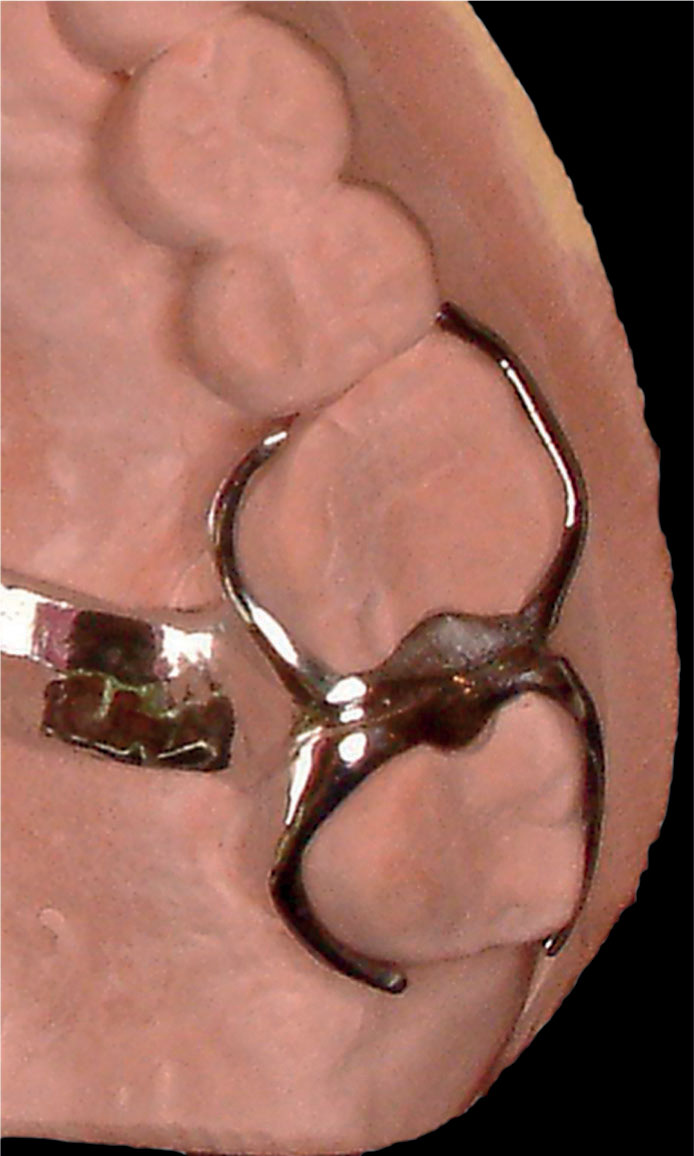
The intricate close-fitting design of a final CoCr framework (Figure 3) is such that should one of the abutment teeth fracture, it is very difficult to provide an indirect crown that fits the tooth as well as the existing framework. Problems encountered can be lack of retention and/or rocking of the denture, or worse still, the denture not fitting at all. If the attempt fails, a lot of time, effort and money are wasted. Furthermore, there would now be additional costs involved in the provision of the new crown and the new denture.
This Top Tip shows a predictable technique to fabricate a crown that fits the existing CoCr denture: one that is relatively easy and cost effective.
Case presentation
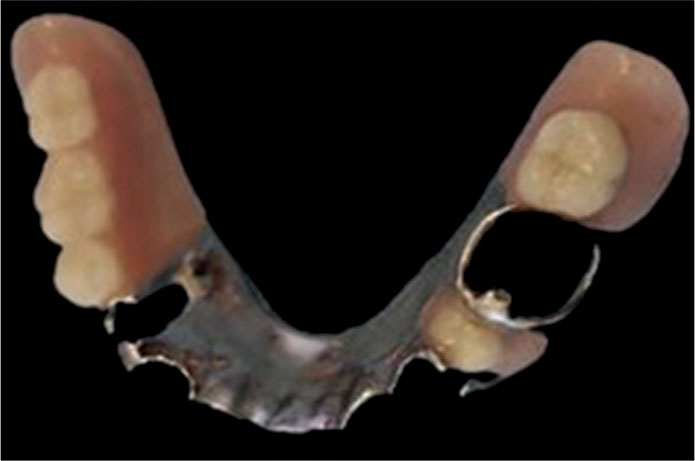
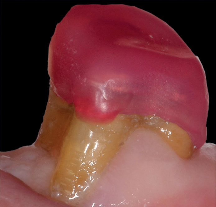
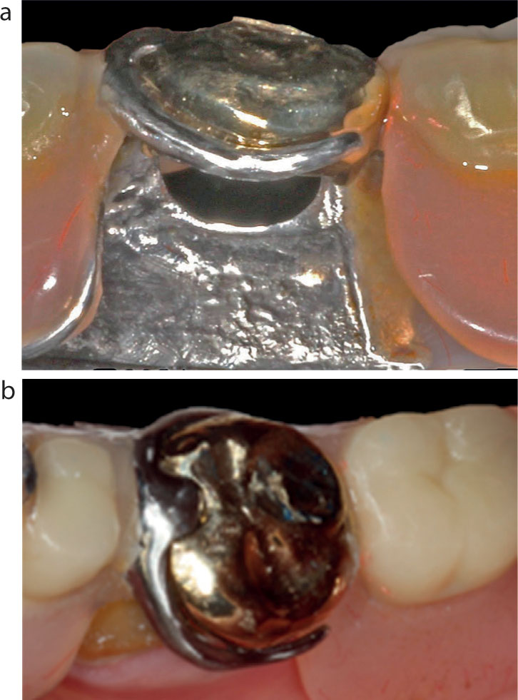
An 83-year-old male patient presented with his denture (Figure 4) in a box because he was unable to fit it into place. The lower left first molar had fractured at a weekend, and the patient had attended an emergency dental practice where the tooth was restored with a large amalgam, which also replaced the fractured buccal cusps. The dentist was unable to shape the restoration to allow the denture to fit as the shape was larger and different to the original tooth. No photo on presentation was taken.
The patient was anxious to have the problem remedied quickly because he was finding it difficult to eat without his denture. In addition, there were financial considerations, and he asked if it would be possible to provide a crown that the denture could fit around, rather than have to pay for both a new crown and denture.
Chosen technique
The treatment plan arrived at was as follows. As an initial emergency step, the existing core was to be reduced until the denture fitted. No attempt was made to match the fit of the clasp/rest seat assembly, so there was no contact between it and the reduced tooth, but at least the patient could eat when the denture was in place.
The technique chosen for the subsequent appointment for the final restoration was to fall back to the use of a traditional method whereby an indirect resin, for example GC Pattern Resin (GC Corporation, Japan) or Duralay (Reliance, Dental Mfg Co, USA), would be used intra-orally and incrementally to build the shape of the desired crown around the clasp assembly onto a prepared resin coping fabricated in the laboratory from the working impression provided. In addition, by placing the soft resin on the occlusal surface of the coping, a functionally generated path created by the opposing teeth in excursive mandibular movements would reproduce the occlusal scheme required to fit in with the remaining dentition, leaving few if any adjustments needed at the fit stage.1,2
It was the opinion of the authors that the preferable material of choice would be gold because building a new crown with a conventional porcelain-fused-to-metal crown would be virtually impossible with the multilayering of feldspathic porcelain required to achieve a close fit for the clasp and rest seat assembly. A pressed lithium disilicate restoration would also have been an alternative option had aesthetics been a priority (milled restorations are discussed later). The other options considered were:
Clinical steps
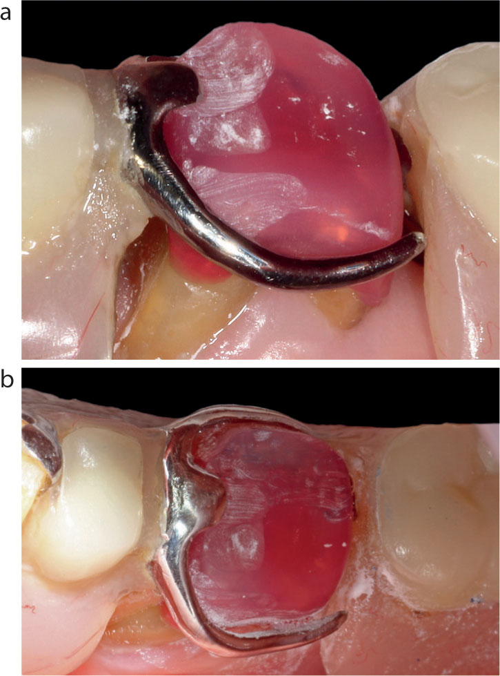
The recently provided amalgam restoration was deemed satisfactory to be used as a core for the new crown and was prepared at the following appointment, a working impression taken and a temporary crown fitted and trimmed accordingly to allow the denture to fit passively enabling the patient to eat while wearing it. During the preparation of the tooth, it was essential to keep trying in the denture to ensure that sufficient space existed between the preparation and the clasp/rest seat assembly for the proposed new crown (Figure 5).
The final tooth preparation for a full gold crown with bevelled margins is shown in Figure 6a, with the working die poured from the impression by the technician in Figure 6b.
The technician was asked to create a thin coping in GC Pattern Resin, as thin as possible but without sacrificing rigidity. The trial fitting on the prepared tooth to check marginal accuracy, fit and stability is shown in Figure 7.
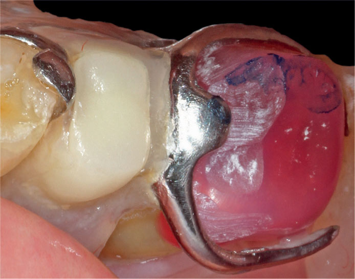
The next step was to fit the denture into place and check that sufficient space existed between the clasp/rest seat assembly and the coping. Adjustments were made as necessary to achieve this clearance, with particular attention being paid in the area of the rest seat. Figure 8 shows the clearance created between the coping, rest seat and clasp (the lingual side was also checked to ensure similar spacing).
Articulating paper was used to identify contacts in intercuspal, lateral, and protrusive mandibular excursions. These were adjusted to ensure adequate occlusal clearance between the coping and opposing teeth (Figure 9).
With this technique, additions to the coping are made incrementally starting with the occlusal surface. As a first step, to avoid the GC Pattern Resin ‘sticking’ to the opposing dentition, it is recommended that the occlusal surfaces are covered with a thin layer of Vaseline.
The subsequent step with this technique is to apply a tiny bit of ‘sludgy’ consistency resin in the area of the rest seat and place the denture in its correct position keeping it firmly in place until the resin has set. Once set, any excess is removed and the denture replaced to ensure it is stable in situ and not rocking.
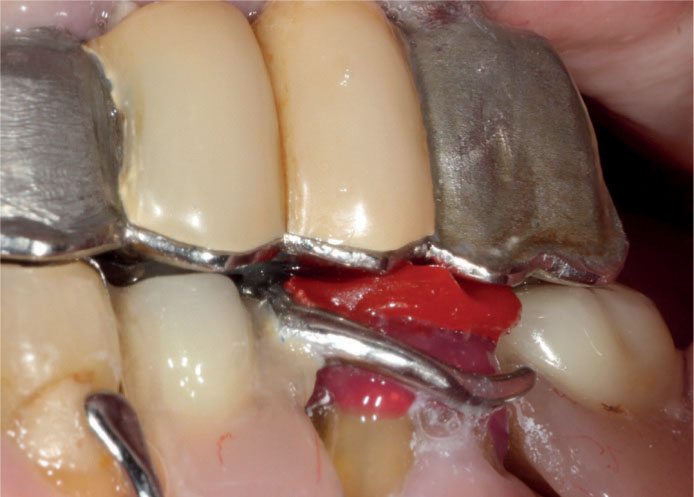
The next step is to create the occlusal surface. Again, the resin is mixed to a shiny, sludgy consistency and applied to the occlusal surface, and the patient instructed to close and move into all excursive movements – backwards, forwards and side to side – until the resin has set (Figure 10).
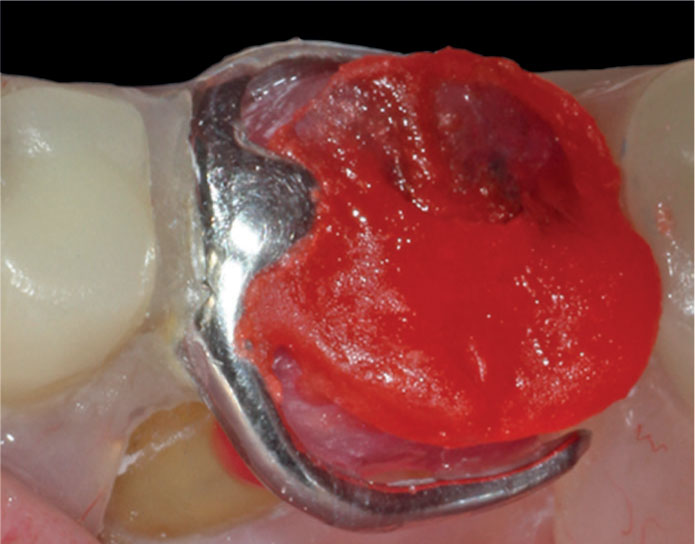
As a tip, if there is an excess of material encroaching onto the clasps, remove it from the coping while soft with a probe or a scaler before it polymerizes. The ideal is to be completely clear of the buccal surfaces (Figure 11).
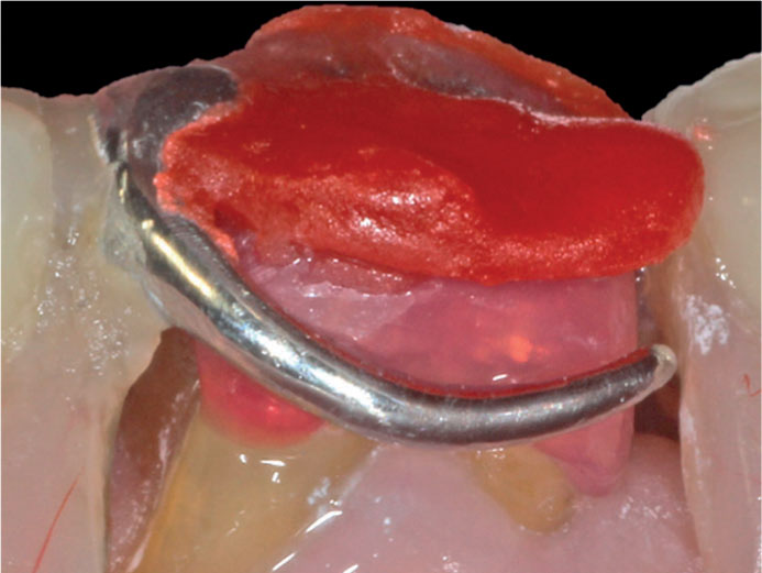
The resultant occlusal surface generated is shown in Figure 12. The denture should be removed and replaced to ensure ease of seating and accuracy of fit for the next phase. The coping often comes out with the denture, if so, wiggle it gently until it pops out (do not lever it out as it may break). There should be a tight fit between the coping and the denture. At this point the occlusion should be rechecked on the coping to ensure it is correct, preferably using shimstock and checking holds on the natural teeth as well as the coping. Any required adjustments to the occlusal surface of the coping should be made at this point.
The coping is then removed from the denture and contoured to remove the excess resin material to ‘mimic’ the shape of a molar tooth (Figure 13a). The coping is then replaced into the clasp assembly to verify accuracy of fit and stability and then fitted in the mouth and the occlusion rechecked (Figure 13b).
All that remains to be carried out, with the resin coping in situ in the denture, is to add resin to the contours between the clasp and the occlusal surface both buccally and lingually and below the clasps, if required, to improve the contours in that area. This can be carried out intraorally but is fiddly and time consuming. If the coping is secure and not moving, this stage can be carried out chairside or sent along with the denture to the technician to refine, invest and cast (Figure 14). In this case, this step was carried out chairside so the patient could continue to use the denture while the new crown was being fabricated by the laboratory.
The coping, or entire denture coping assembly, is returned to the technician. In this case, it was just the coping that was sent. The technician then went through the various steps to cast the crown in conventional fashion, finalizing and polishing the crown. If a pressed lithium disilicate is the desired material for aesthetic reasons, then the usual laboratory protocols for this material are followed for fabrication. If a milled restoration is the preferred option, then the coping would be scanned on the working model and the usual steps followed to fabricate the crown. It is the authors' opinion that the intricate customized shape of the milled restoration may not be quite as well reproduced as the cast or pressed option and runs the risk of the clasp/rest seat assembly being loose. Generally, bending CoCr clasps to improve retention is inadvisable, as they may break.
Figure 15 shows the intricate shape of the new crown to accommodate the clasp/rest seat assembly. As the laboratory did not have the denture, the fit of the crown was checked chairside against the denture. Adjustment is only rarely necessary to make the fit accurate. As the occlusion had already been refined intra-orally using the functionally generated path technique, alterations to the occlusal scheme are also usually not necessary or negligible.
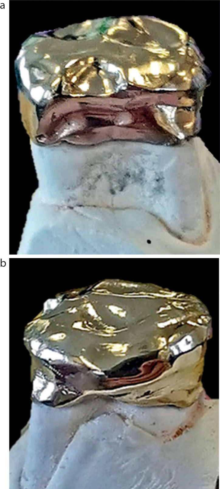
Figure 16 shows the crown cemented in place with Relyx Unicem (3M) and the accurate fit of the denture in situ.
Conclusions
A technique to fabricate a crown to fit accurately around the clasp/rest seat assembly of an existing CoCr denture is demonstrated. The technique is very predictable, and as the current denture continued to be used, the patient had only to pay for the new crown.